 The motors

Small, high-reving, brushless geared motors were used in
1926 already - alas only in the Göttingen wind tunnel (see also The Gallery). It should take a long
time until those were finally fit to fly aboard a model airplane.
Our F5B planes are powered by
brushless Kontronik and MEB electric motors. While information
about Kontronik motors and speed controllers is available
directly from Kontronik (phone +49-7457-94350, fax
+49-7457-943590, Kontronik
website), we'd like to show a few pictures of the motors we
develop and build in cooperation with MEB (Edwin Bloch, phone
+49-7457-5770, fax +49-7457-5880). These are lavish and
non-compromising motors which look kinda weird - no glossy
finish, no plugs between motor and controller etc., so they
definitely won't tickle everybody's fancy. Nevertheless, these
will be available if there's enough interest.
Motor length excluding shaft:: approx. 80 mm, largest
diameter: 33 mm, weight: approx. 230 grams.
 |
Side view - which shows the general layout. Left to
right: 6 mm output shaft, carbon gearbox casing,
steel ring gear for the planetary gearbox, front flange
(wound from Kevlar/Aramide), iron rings (held together by
glass and Kevlar/Aramide strips), rear flange (wound from
Kevlar/Aramide). |
 |
Front view. |
 |
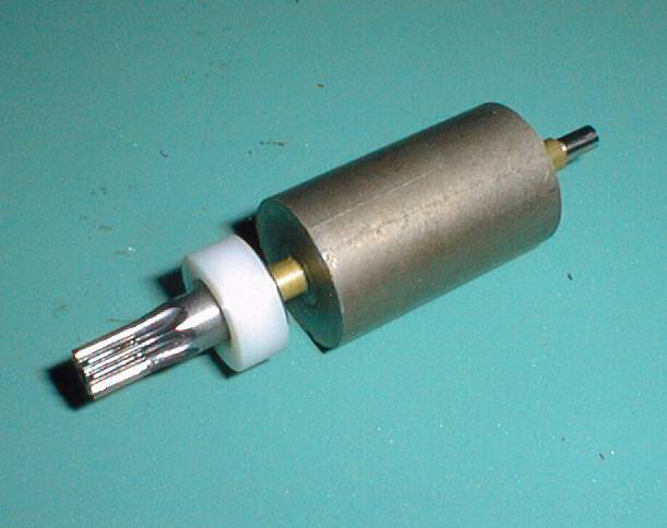
The rotor (solid Neodymium) with front bearing and
pinion. |
 |
Motor front, gearbox opened. |
 |
Motor rear with aft bearing and hall sensors. Part of
the copper windings can be seen inside the motor case.
The windings are mounted together with the iron rings,
insulating layers and the front and rear flange parts,
then reinforced and wound with Kevlar/Aramide and cured
in an oven. A high temperature resin makes for maximum
heat resistance. |
 |
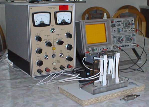
Balancing machine with power supply and oszilloscope.
The rotor is driven by a small electric motor and a
rubber band. Because of the strong magnetic field of the
rotor, the balancing machine had to be constructed
exclusively from plastics and other non-magnetic
materials. |
 |
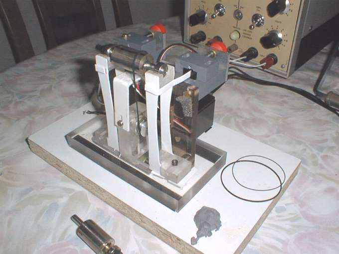
The rotor bearings are held by parallelogram supports
which allow them to move sideways. Any imbalance results
in horizontal vibrations which are detected by
photoelectric beams and viewed on an oscilloscope. Below
the rotor, a light reflection sensor points at felt-tip
pen markings (wide line at 0°, narrow lines at 90°,
180° and 270°) which are viewed on the oscilloscope
too. This way, the exact position of the imbalance can be
determined easily. |
Home | Up | DEUTSCH (Hannes
Delago - Feb 5, 1997 / May 11, 1997)